Installation instructions
Built-in tracker Ebike Pro
Always have the installation carried out by a professional! Incorrect connection of the tracker can cause damage to both the bicycle and the tracker.
Is this my type of tracker?
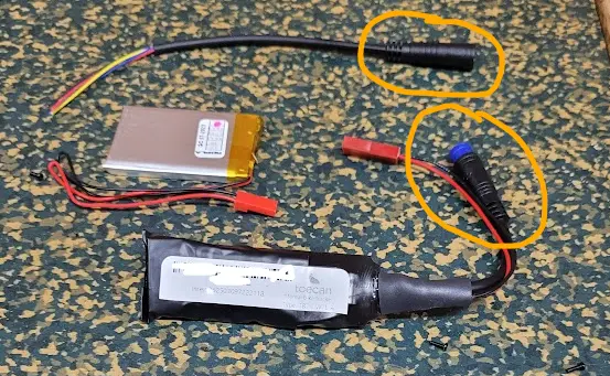
The internal tracker Ebike Pro can be recognized by the protective shrink tubing, the external battery and the blue-black connector. See photo below for an example. If your tracker meets this description, this page describes how the tracker is connected.

Connection diagram

Tracker Status check tool
With the Tracker status check tool it is possible to verify the status of the tracker in real time. This is very useful during installation to verify that the tracker has been connected correctly and is functioning properly.

The tool is publicly accessible, but a valid tracker code must be entered to display the results. Privacy-sensitive information is not displayed on the public tool.
Step-by-step plan
Step 1
Validate that all components are present before installation:
- Tracker
- External battery
- 3 T-connectors
- Female connector with open end
T-connectors are supplied as standard to branch off power from existing wiring. It is not necessary to cut the existing wiring, but a small cut is made in the ferrule!
In addition to the T-connectors, it is also possible to solder the wiring, or use a plug-and-play adapter piece for your specific type of bicycle (available separately).

Step 2
Place the red and black wires of the open-ended connector in the T-connector.
To ensure good contact between the T-connector and the wiring, it is recommended to first strip the cores and then fold them back so that the conductor from the core already makes contact with the metal in the T-connector.

Step 3
Use pliers to push the T-connector closed. The idea is that the core from the open-ended connector gets stuck in the recess of the metal part of the T-connector.

Step 4
Open the T-connector again.
Always check whether good contact is made between the conductor and the T-connector!

Step 5
Find a suitable power source. The tracker has a wide input range (9-90VDC). This means you can also tap directly into battery voltage, but also into the power supply for the display or other modules.

Step 6
Place the unfolded T-connector over the wiring that will be branched off. The recess in the metal part should be above the guide.

Step 7
Use pliers to pinch the T-connectors closed. Check whether the recess in the metal part makes a slip in protection of the conductor.

Step 8
Once the branches have been made, the tracker can be connected to the power supply.
Do not connect the external battery to the tracker yet!

Step 9
After connecting the tracker, the tracker status check tool can be used to check whether the connection is successful.
After connecting to the external power source, the tracker should boot up and report a data point.
- The "Last Online" indicator should turn green
- Battery Charging should display "True" and turn green
- Record Battery Percentage
This step is necessary to verify that the tracker was connected successfully.
To speed up this procedure, you can briefly shake the tracker, in this way a vibration warning is generated and the position is uploaded.
Connect the external battery only after successful connection of the external power has been verified.
If the external battery is already connected, the tracker will start up using the battery power.

Step 10
Connect the external battery to the tracker.

Step 11
Compare the battery percentage before and after plugging in the battery (the status check must be performed again), the percentage should have increased.
